Septa (SE)

SE

Design development, construction, installation, exploitation & maintenance, across the entire accelerator complex of:


  • Electrostatic septa (thin foil, wire) and electric field devices, including their high voltage circuitry;
  • Magnetic septa (thin-coil direct-drive, eddy-current septa);
  • Laminated steel fast bumpers (under and out of vacuum);
  • Injection and extraction related special systems (protection elements, stripping foils, ion traps,…);
  • Associated positioning systems.

For more information, please click on the following link, which will send you to the SharePoint site.

Examples:

Electrostatic septa

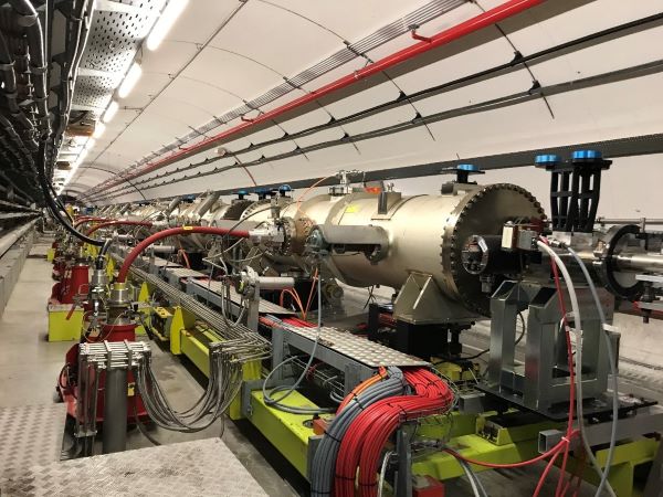
Electrostatic septa are devices that deflect particle beam using an electric field. This allows for only a very thin separation between the field free region and the high field region (see link for a general explanation). Recently the 5 electrostatic septa installed in the SPS were upgraded to improve their beam impedance as well as to improve their operation vacuum. To this end new impedance screens we designed and installed in each septum tank and these tanks were connected between each other using newly designed interconnects which preserve as well as possible the beam impedance. Vacuum was improved by the installation of ion pumps which are equipped with additional NEG cartridges. Together with the much improved location of these pumps, the pumping speed available in the septa vacuum vessels was significantly increased.

The image below shows the new set of electrostatic septa installed in the SPS, together with their High Voltage (HV) connections.

Electrostatic septa

Magnetic Septa

Magnetic septa are dipole magnets that deflect the particle beam entering or exiting a synchrotron accelerator, while making sure that the adjacent orbiting beam already present in the accelerator is not affected.

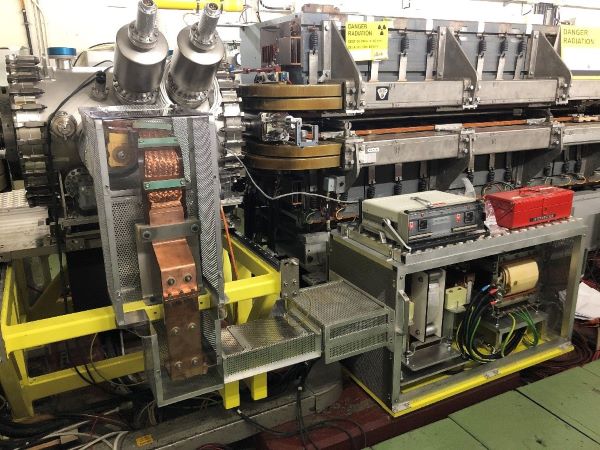
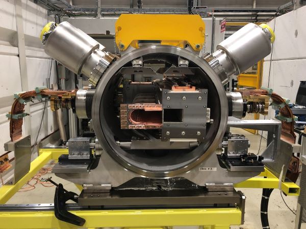
A recent development concerned the injection of 2 GeV protons into the PS accelerator. The robust ‘eddy current septum’ topology was chosen for this application, but to limit the voltage required on the device while still achieving the large current needed to produce the magnetic field, this topology was adapted to allow pulsing with much longer pulses than is typically used.

The first image below shows the system installed in the PS ring, while the second image show the vacuum vessel with the magnets inserted prior to tank closing. Of note are the sizable copper electrical connections.

Magnetic Septa 1

Magnetic Septa

Magnetic septa are dipole magnets that deflect the particle beam entering or exiting a synchrotron accelerator, while making sure that the adjacent orbiting beam already present in the accelerator is not affected.

A recent development concerned the injection of 2 GeV protons into the PS accelerator. The robust ‘eddy current septum’ topology was chosen for this application, but to limit the voltage required on the device while still achieving the large current needed to produce the magnetic field, this topology was adapted to allow pulsing with much longer pulses than is typically used.

The first image below shows the system installed in the PS ring, while the second image show the vacuum vessel with the magnets inserted prior to tank closing. Of note are the sizable copper electrical connections.

Magnetic Septa 2

Laminated outside vacuum bumpers and septa

To allow injection of the H- beam into the PS Booster from LINAC 4, each ring is equipped with a set of magnetic bending magnets that allow the orbiting proton beam to merge with the incoming H- beam and pass through the stripping foil to transform the H- ion into a proton by removing the 2 electrons. The challenge for this project resided in fitting 16 magnets in a space previously occupied by only 4 magnetic septa. The mechanical integration and the possibility to remove a magnet and replace by a spare without the need for further alignment called for a very compact design. All magnets were designed, but also construction in-house.

The photograph below shows the final installation of these blue magnets, but the image is dominated by the copper electrical connections of each magnet.

Laminated outside vacuum bumpers and septa

Extraction protection systems

To protect the septum conductor from an accidentally mis-steered beam, protection elements are place in front of the some septa. The elements dilute the beam that would otherwise impact directly on the septum conductor. The beam is sufficiently diluted to avoid irreversible damage to the protection element as well as the downstream septum magnet.  

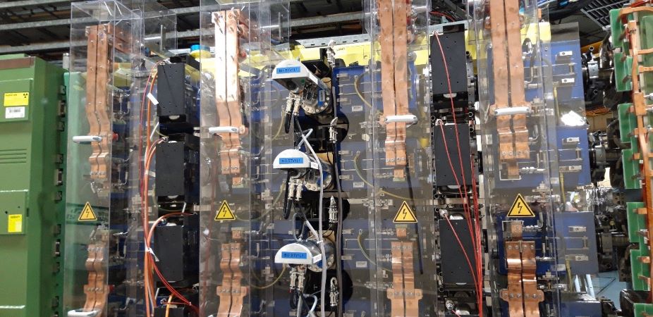
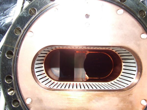
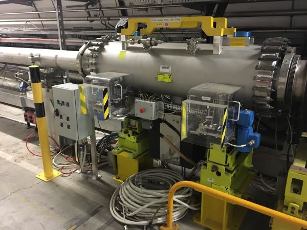
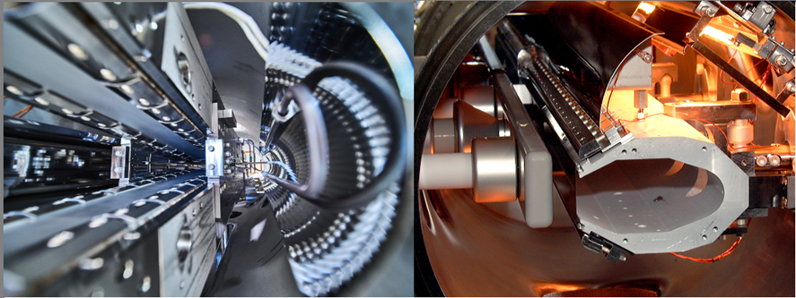
The photo below shows the TCDS used in the LHC. The passage for the orbiting beam (right) and the extracted beam (left) is separated by a high tech carbon composite which dilutes the beam in case of accidental impact. The second photograph shows a diluter in the SPS which can be remotely adjusted (with the motorisation system behind the transparent covers) with respect to the beam, to allow for the best possible protection of a downstream septum magnet.

Extraction protection systems 1

Extraction protection systems

To protect the septum conductor from an accidentally mis-steered beam, protection elements are place in front of the some septa. The elements dilute the beam that would otherwise impact directly on the septum conductor. The beam is sufficiently diluted to avoid irreversible damage to the protection element as well as the downstream septum magnet.  

The photo below shows the TCDS used in the LHC. The passage for the orbiting beam (right) and the extracted beam (left) is separated by a high tech carbon composite which dilutes the beam in case of accidental impact. The second photograph shows a diluter in the SPS which can be remotely adjusted (with the motorisation system behind the transparent covers) with respect to the beam, to allow for the best possible protection of a downstream septum magnet.

Extraction protection systems 2