Beam Transfer Electronics (BTE)

BTE

The BTE Section is responsible for the design, development, production, exploitation, quality assurance, performance follow-up and maintenance of controls electronics for all equipment under the responsibility of the ABT group and associated R&D activities.

The responsibilities include:

  • Electronics design (analog, digital and mixed) including gateware and firmware;
  • Dedicated high-voltage low power pulsed generators and special actuators and sensors;
  • Triggering systems for thyratron and solid state switches;
  • LV & HV capacitor charger power supplies and HVDC power generator;
  • Electronic modules and enclosure production, test and maintenance;
  • Participation to the stand by kicker service and ABT equipment operational responsibility role.

Examples:

ZS ION TRAPS

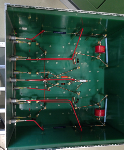
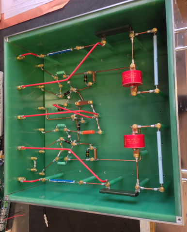
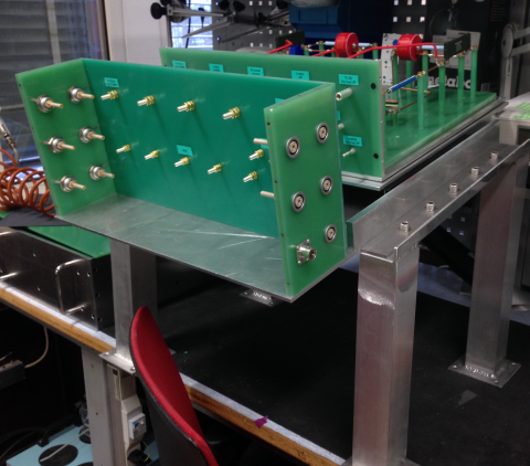
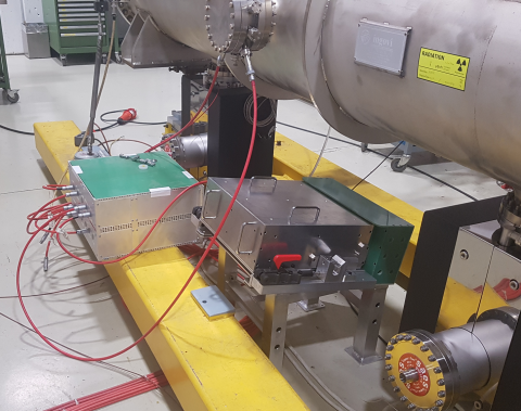
The ion traps are cleaning electrode devices placed in the ZS field-free region containing the circulating beam. They remove ions produced by beam interactions within the residual gas molecules to protect the equipment against the sparking effects. Ion traps HV boxes are interconnect systems placed below the septa tanks that interface the controls and HV distributions to and from the ion trap structures inside the septa tanks. The ‘old’ HV box design has been flawed by many problems related to its past intrinsic original design combined with reliability issues. Upgrades and improvements have been necessary to create the new of ion traps HV box.

iontrap1

ZS ION TRAPS

The ion traps are cleaning electrode devices placed in the ZS field-free region containing the circulating beam. They remove ions produced by beam interactions within the residual gas molecules to protect the equipment against the sparking effects. Ion traps HV boxes are interconnect systems placed below the septa tanks that interface the controls and HV distributions to and from the ion trap structures inside the septa tanks. The ‘old’ HV box design has been flawed by many problems related to its past intrinsic original design combined with reliability issues. Upgrades and improvements have been necessary to create the new of ion traps HV box.

iontrap2

ZS ION TRAPS

The ion traps are cleaning electrode devices placed in the ZS field-free region containing the circulating beam. They remove ions produced by beam interactions within the residual gas molecules to protect the equipment against the sparking effects. Ion traps HV boxes are interconnect systems placed below the septa tanks that interface the controls and HV distributions to and from the ion trap structures inside the septa tanks. The ‘old’ HV box design has been flawed by many problems related to its past intrinsic original design combined with reliability issues. Upgrades and improvements have been necessary to create the new of ion traps HV box.

iontrap3

ZS ION TRAPS

The ion traps are cleaning electrode devices placed in the ZS field-free region containing the circulating beam. They remove ions produced by beam interactions within the residual gas molecules to protect the equipment against the sparking effects. Ion traps HV boxes are interconnect systems placed below the septa tanks that interface the controls and HV distributions to and from the ion trap structures inside the septa tanks. The ‘old’ HV box design has been flawed by many problems related to its past intrinsic original design combined with reliability issues. Upgrades and improvements have been necessary to create the new of ion traps HV box.

iontraps_under_ZS_tank

LHC Beam Dumping System generators

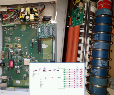
The LHC Beam Dumping System (LBDS) is a critical system, ensuring safe extraction of the beam from LHC. The beam is sent to the extractionchannel using 15 extraction kicker magnets and 15 extraction septa; it is then diluted by 4 horizontal and 6 vertical dilution magnets on the beam dump absorber.

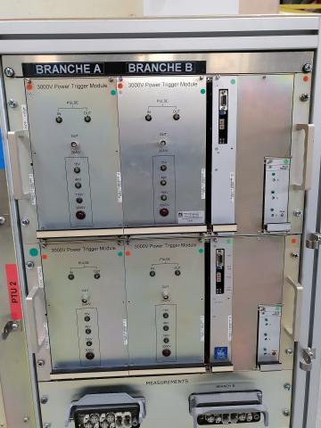
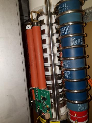
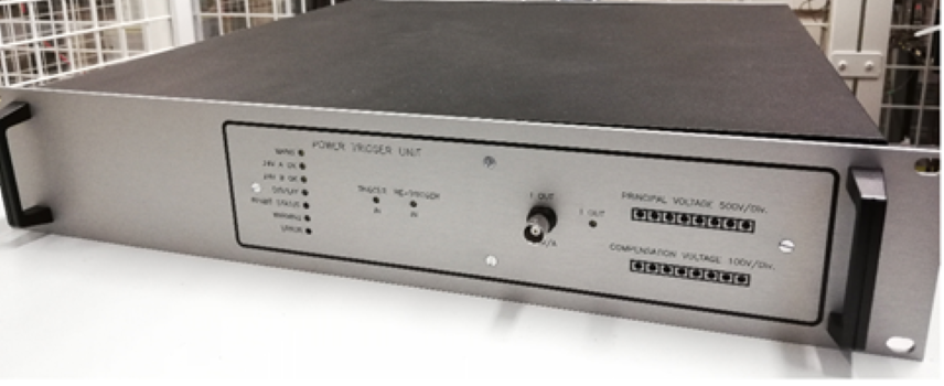
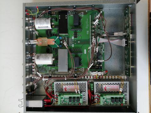
On the pictures one can see subparts of the High Voltage Pulsed Generators that power these kicker magnets. The Power Trigger Modules (PTM) will start the conduction of the two redundant switches composed of a stack of Fast High Current Thyristors that discharge capacitors into the magnet. The BTE section provides the high-voltage PTM and custom electronics to provide surveillance and interlocking functionality.

LBDS - Power Trigger Unit

LHC Beam Dumping System generators

The LHC Beam Dumping System (LBDS) is a critical system, ensuring safe extraction of the beam from LHC. The beam is sent to the extractionchannel using 15 extraction kicker magnets and 15 extraction septa; it is then diluted by 4 horizontal and 6 vertical dilution magnets on the beam dump absorber.

On the pictures one can see subparts of the High Voltage Pulsed Generators that power these kicker magnets. The Power Trigger Modules (PTM) will start the conduction of the two redundant switches composed of a stack of Fast High Current Thyristors that discharge capacitors into the magnet. The BTE section provides the high-voltage PTM and custom electronics to provide surveillance and interlocking functionality.

LDBS - Stack Divider Converter

LHC Beam Dumping System generators

The LHC Beam Dumping System (LBDS) is a critical system, ensuring safe extraction of the beam from LHC. The beam is sent to the extractionchannel using 15 extraction kicker magnets and 15 extraction septa; it is then diluted by 4 horizontal and 6 vertical dilution magnets on the beam dump absorber.

On the pictures one can see subparts of the High Voltage Pulsed Generators that power these kicker magnets. The Power Trigger Modules (PTM) will start the conduction of the two redundant switches composed of a stack of Fast High Current Thyristors that discharge capacitors into the magnet. The BTE section provides the high-voltage PTM and custom electronics to provide surveillance and interlocking functionality.

PTC

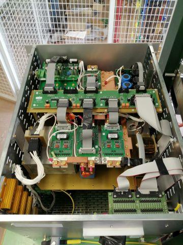
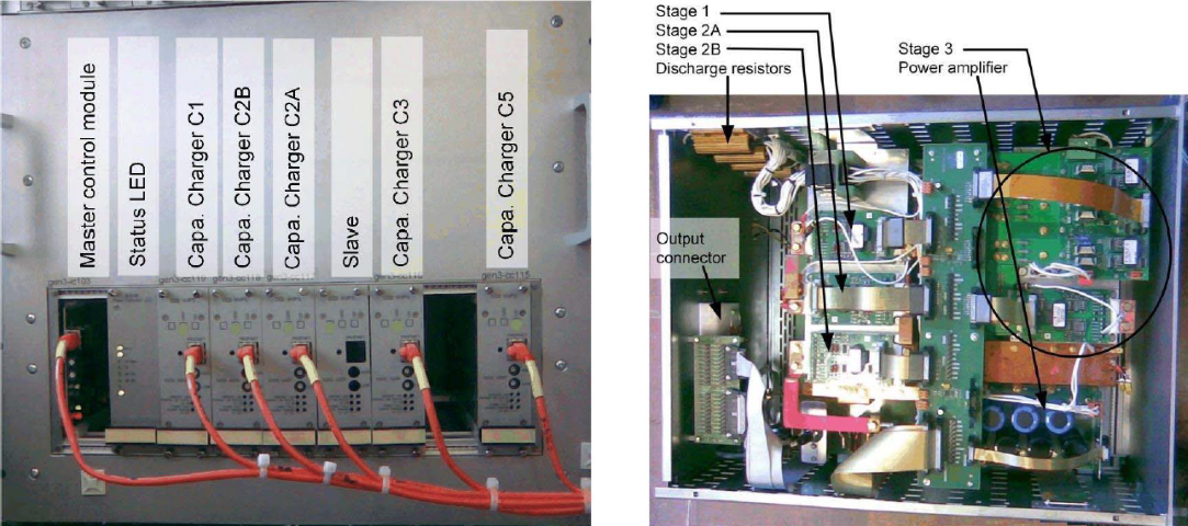
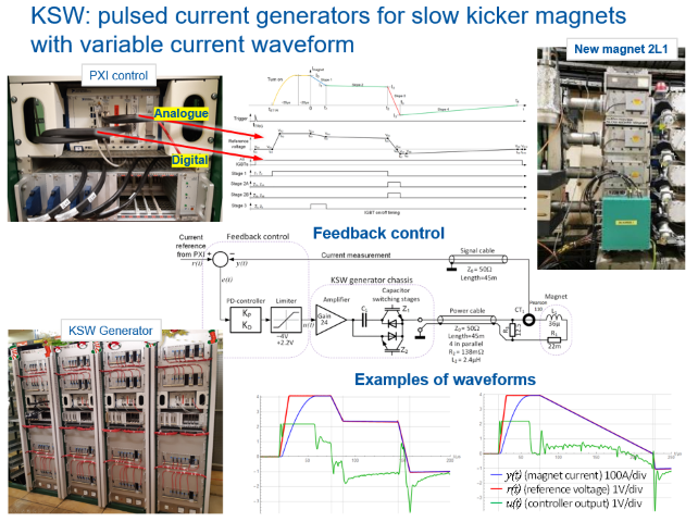
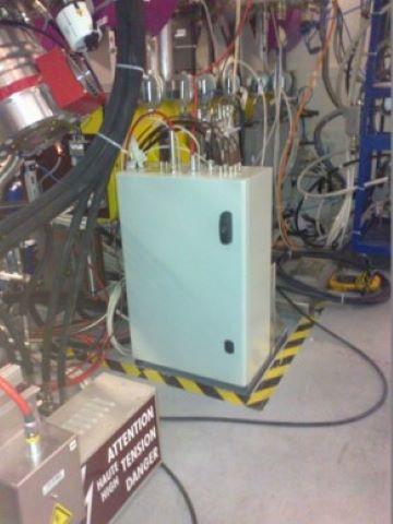
A multi-waveform pulsed current generator for slow kicker magnets.

As part of the LIU project at CERN pulsed magnet current generators for phase space painting of the PSB accelerator were developed that generate pulse to pulse programmable waveforms comprising four linear slopes of variable length. A high current generator with a peak current of 400A and a low current version with 40A were developed. Amplitude tolerance is <1%. The waveforms are generated by connecting pre-charged capacitors to the magnet to make the current rise or fall. The final precision is controlled with a feedback loop and a linear class AB power amplifier. Special capacitor charger modules were developed that allow fast up/down voltage adjustment of the capacitors.

ksw 1

A multi-waveform pulsed current generator for slow kicker magnets.

As part of the LIU project at CERN pulsed magnet current generators for phase space painting of the PSB accelerator were developed that generate pulse to pulse programmable waveforms comprising four linear slopes of variable length. A high current generator with a peak current of 400A and a low current version with 40A were developed. Amplitude tolerance is <1%. The waveforms are generated by connecting pre-charged capacitors to the magnet to make the current rise or fall. The final precision is controlled with a feedback loop and a linear class AB power amplifier. Special capacitor charger modules were developed that allow fast up/down voltage adjustment of the capacitors.

ksw 2

A multi-waveform pulsed current generator for slow kicker magnets.

As part of the LIU project at CERN pulsed magnet current generators for phase space painting of the PSB accelerator were developed that generate pulse to pulse programmable waveforms comprising four linear slopes of variable length. A high current generator with a peak current of 400A and a low current version with 40A were developed. Amplitude tolerance is <1%. The waveforms are generated by connecting pre-charged capacitors to the magnet to make the current rise or fall. The final precision is controlled with a feedback loop and a linear class AB power amplifier. Special capacitor charger modules were developed that allow fast up/down voltage adjustment of the capacitors.

ksw 3

Linac4 Prechopper

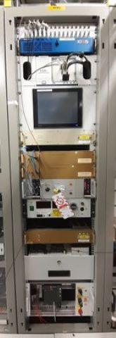
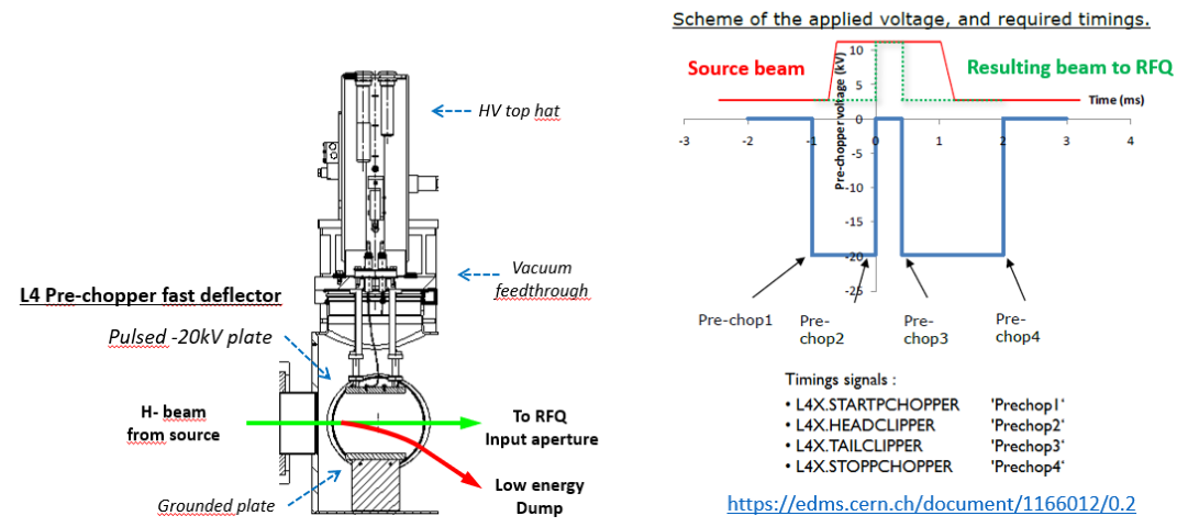
The Pre-chopper is located in the Linac4 LEBT, and deflects the beam away from the RFQ input aperture when it is not required. It serves to reduce the beam start up time from the source, shorten the pulse length from the source, and as a compliment to the chopper, stop the beam due to machine interlocks. This is done by applying ~-20kV to a plate in vacuum, which is switched to 0V when the beam should pass.

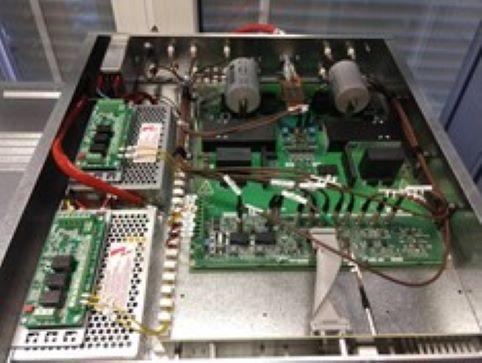
BTE has provided the high-voltage generator and controls, based on COTS and custom hardware.

Linac 1

Linac4 Prechopper

The Pre-chopper is located in the Linac4 LEBT, and deflects the beam away from the RFQ input aperture when it is not required. It serves to reduce the beam start up time from the source, shorten the pulse length from the source, and as a compliment to the chopper, stop the beam due to machine interlocks. This is done by applying ~-20kV to a plate in vacuum, which is switched to 0V when the beam should pass.

BTE has provided the high-voltage generator and controls, based on COTS and custom hardware.

Linac 2

Linac4 Prechopper

The Pre-chopper is located in the Linac4 LEBT, and deflects the beam away from the RFQ input aperture when it is not required. It serves to reduce the beam start up time from the source, shorten the pulse length from the source, and as a compliment to the chopper, stop the beam due to machine interlocks. This is done by applying ~-20kV to a plate in vacuum, which is switched to 0V when the beam should pass.

BTE has provided the high-voltage generator and controls, based on COTS and custom hardware.

Linac 3

SPS Beam Dumping System - Power Trigger Module

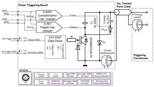
In order to prevent uncontrolled beam losses in the Super Proton Synchrotron (SPS) at CERN,  which  can  cause  thermal and radiation  damages  to  machine components,  an internal beam dumping system is used. Upgraded layout will consists of three fast-pulsed magnets that deflect the circulating beam vertically and three that sweep it in horizontal axis onto an absorber block within one accelerator revolution. The excitation current for each magnet is generated by the discharge of a Pulse Forming Network (PFN) through the  magnet  into  a  matched  terminating  resistor.  As  triggering  circuits  are  one  of  the most critical components that will determine the global performance of a pulsed power system, a matched triggering system with the stacks of GTOs (Gate Turn-Off Thyristors) has been developed with the objectives to improve the switching performance.

sptm 1

SPS Beam Dumping System - Power Trigger Module

In order to prevent uncontrolled beam losses in the Super Proton Synchrotron (SPS) at CERN,  which  can  cause  thermal and radiation  damages  to  machine components,  an internal beam dumping system is used. Upgraded layout will consists of three fast-pulsed magnets that deflect the circulating beam vertically and three that sweep it in horizontal axis onto an absorber block within one accelerator revolution. The excitation current for each magnet is generated by the discharge of a Pulse Forming Network (PFN) through the  magnet  into  a  matched  terminating  resistor.  As  triggering  circuits  are  one  of  the most critical components that will determine the global performance of a pulsed power system, a matched triggering system with the stacks of GTOs (Gate Turn-Off Thyristors) has been developed with the objectives to improve the switching performance.

sptm 2

SPS Beam Dumping System - Power Trigger Module

In order to prevent uncontrolled beam losses in the Super Proton Synchrotron (SPS) at CERN,  which  can  cause  thermal and radiation  damages  to  machine components,  an internal beam dumping system is used. Upgraded layout will consists of three fast-pulsed magnets that deflect the circulating beam vertically and three that sweep it in horizontal axis onto an absorber block within one accelerator revolution. The excitation current for each magnet is generated by the discharge of a Pulse Forming Network (PFN) through the  magnet  into  a  matched  terminating  resistor.  As  triggering  circuits  are  one  of  the most critical components that will determine the global performance of a pulsed power system, a matched triggering system with the stacks of GTOs (Gate Turn-Off Thyristors) has been developed with the objectives to improve the switching performance.

sptm 3

SPS Beam Dumping System - Power Trigger Module

In order to prevent uncontrolled beam losses in the Super Proton Synchrotron (SPS) at CERN,  which  can  cause  thermal and radiation  damages  to  machine components,  an internal beam dumping system is used. Upgraded layout will consists of three fast-pulsed magnets that deflect the circulating beam vertically and three that sweep it in horizontal axis onto an absorber block within one accelerator revolution. The excitation current for each magnet is generated by the discharge of a Pulse Forming Network (PFN) through the  magnet  into  a  matched  terminating  resistor.  As  triggering  circuits  are  one  of  the most critical components that will determine the global performance of a pulsed power system, a matched triggering system with the stacks of GTOs (Gate Turn-Off Thyristors) has been developed with the objectives to improve the switching performance.

sptm  4

Fast Interlocks Detection System

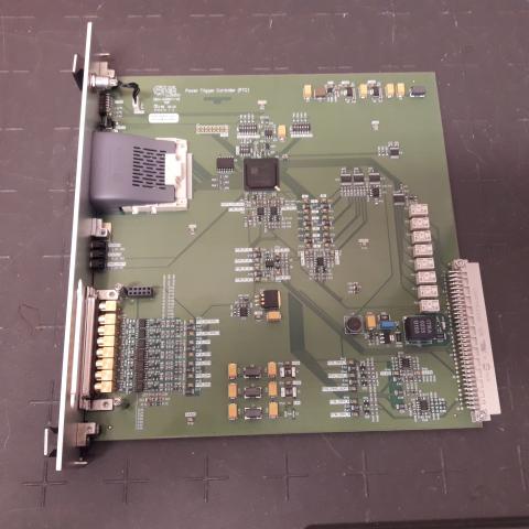
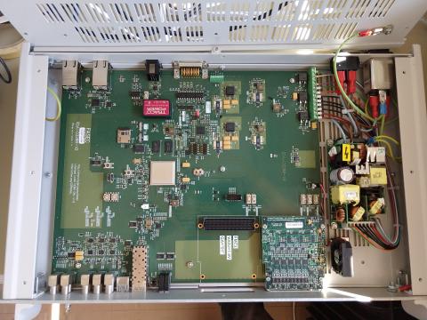
Fast pulsed kicker magnet systems are powered by high-voltage and high-current pulse generators with adjustable pulse length and amplitude. To deliver this power, fast high-voltage switches such as thyratrons and GTOs are used to control the fast discharge of pre-stored energy. To protect the machine and the generator itself against internal failures of these switches several types of fast interlocks systems are used at. To get rid of this heterogeneous situation, a modular digital Fast Interlock Detection System (FIDS) has been developed in order to replace the existing fast interlocks systems. In addition to the existing functionality, the FIDS system will offer new functionalities such as extended flexibility, improved modularity, increased surveillance and diagnostics, contemporary communication protocols and automated card parametrization. A XilinxZynq®-7000 SoC has been selected for implementation ofthe required functionalities so that the FPGA (Field Programmable Gate Array) can hold the fast detection and interlocking logic while the ARM®processors allow for aflexible integration in CERN’s Front-End Software Architecture (FESA) framework, advanced diagnostics andautomated self-parametrization.

The BTE section has developed, next to the gateware and embedded software, two in-house electronic cards for this project which are shared publically at:
https://ohwr.org/project/fasec/wikis/home
https://ohwr.org/project/fmc-dio-10i-8o/wikis/home

fids_fasec