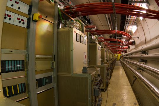
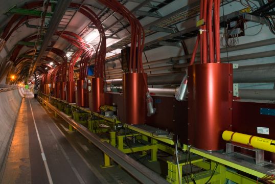
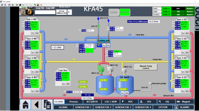
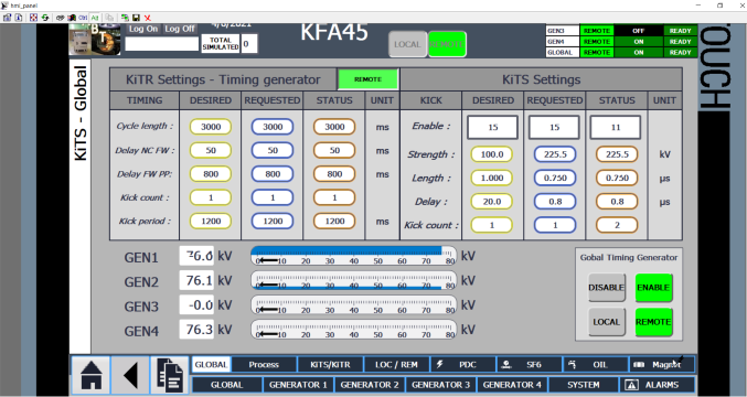
LHC Beam Dump Kicker System Controls:
The performance of the extraction kicker system is determined by three operational parameters: its state, its kick time and its kick strength. To reflect this, its control architecture comprises three independent sub-systems, each one dedicated to the control of one specific parameter:
- The State Control and Surveillance System (SCSS),
- The Trigger Synchronization and Distribution System (TSDS),
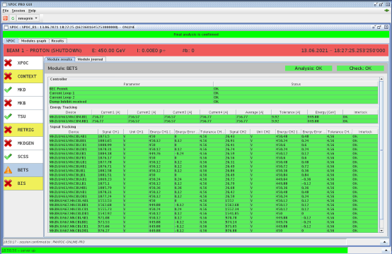
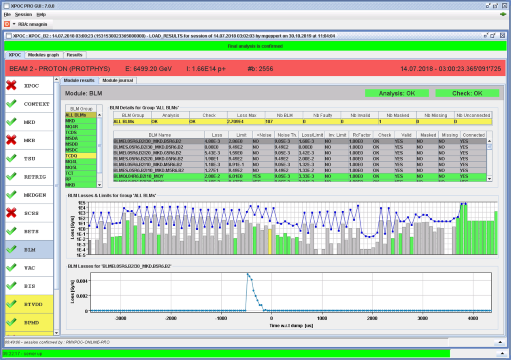
- The Beam Energy Tracking System (BETS)
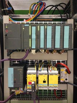
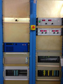
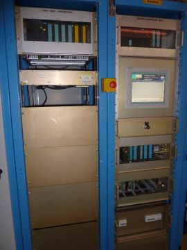
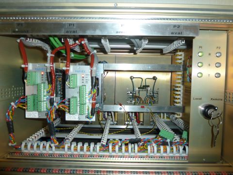
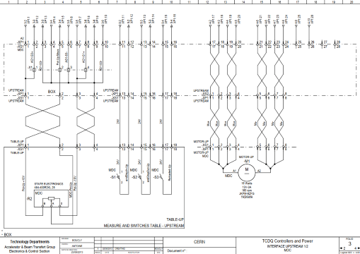
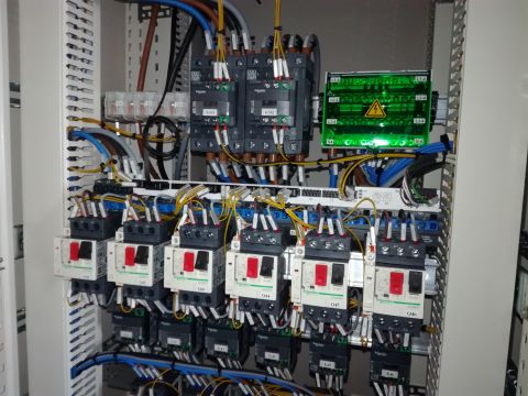
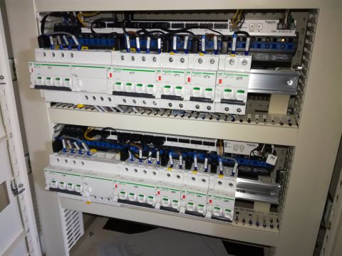
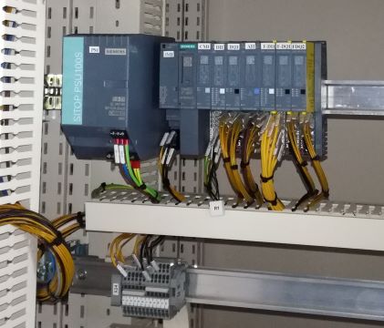
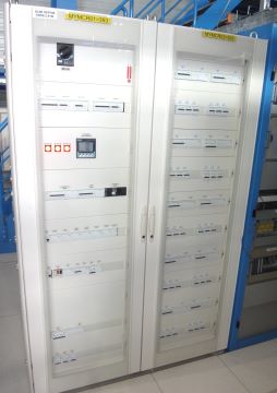
The SCSS is based on a fail-safe multi Programmable Logic Controller (PLC) architecture from Siemens®. It ensures the control of states of the global machine and by individual sub-system. This system ensures also the safety of the machine and the people during the maintenance periods and operational phases. Associated with a fast control, Internal Post-Operation Check (IPOC) and eXternal Post-Operation Check (XPOC), the LBDS can be operated from the LHC control room in security in all modes of operation.